MRMS ESP32: Arduino, IMU, eFuse, BT, WiFi, CAN Bus (mrm-esp32) limitations
| GPIO |
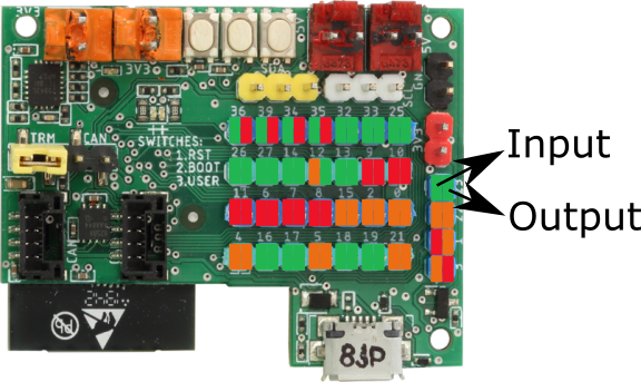
Input |
Output |
Warning |
| 0 |
Yes, but pulled up |
Yes, but read warning |
Outputs PWM signal at boot |
| 1 |
TX pin |
Yes, but read warning |
Debug output at boot |
| 2 |
Yes |
Yes |
Used for on-board LED. 0 Ohm resistor can be removed and then the pin will be completely free. |
| 3 |
Yes, but read warning |
RX pin |
High at boot |
| 4 |
Yes, but only if CAN Bus not used. |
Yes, but only if CAN Bus not used. |
|
| 5 |
Yes, but only if CAN Bus not used. |
Yes, but only if CAN Bus not used. |
Outputs PWM signal at boot |
| 6 |
No |
No |
Usually used for integrated SPI flash. |
| 7 |
No |
No |
Usually used for integrated SPI flash. |
| 8 |
No |
No |
Usually used for integrated SPI flash. |
| 9 |
No |
No |
Usually used for integrated SPI flash. |
| 10 |
No |
No |
Usually used for integrated SPI flash. |
| 11 |
No |
No |
Connected to the integrated SPI flash |
| 12 |
Yes, but read warning |
Yes |
Boot fail if pulled high |
| 13 |
Yes |
Yes |
outputs PWM signal at boot |
| 14 |
Yes |
Yes |
outputs PWM signal at boot |
| 15 |
Yes |
Yes |
Used for on-board LED. 0 Ohm resistor can be removed and then the pin will be completely free. |
| 16 |
Yes |
Yes |
|
| 17 |
Yes |
Yes |
|
| 18 |
Yes |
Yes |
|
| 19 |
Yes |
Yes |
|
| 21 |
Yes |
Yes |
In use for SDA. Therefore, good for I2C, but cannot be used for other purposes. |
| 22 |
Yes |
Yes |
In use for SCL. Therefore, good for I2C, but cannot be used for other purposes. |
| 23 |
Yes |
Yes |
|
| 25 |
Yes |
Yes |
|
| 26 |
Yes |
Yes |
|
| 27 |
Yes |
Yes |
|
| 32 |
Yes |
Yes |
|
| 33 |
Yes |
Yes |
|
| 34 |
Yes, but no software pull-up or pull-down |
No |
Input only |
| 35 |
Yes, but no software pull-up or pull-down |
No |
Input only |
| 36 |
Yes, but no software pull-up or pull-down |
No |
Input only |
| 39 |
Yes, but no software pull-up or pull-down |
No |
Input only |
Green - no limitations, orange some limitations, red - should be avoided.
All output pins are PWM capable, so 34 - 39 are not. All GPIOs pins are interrupt capable.
Here is good reference.
There is a serious limitation to the number of available analog input pins that occurs when You use radio part, WiFi or Bluetooth, as it consumes ADC2. In that case only ADC1 pins remain available, 6 of them: GPIO 32, 33, 34, 35, 36, 39.
Another serious drawback of ESP32's ADC is that it doesn't read small input values. Until up to 0.15 V, the reading will be about 0. To solve this problem, ML-R sensors with analog output offer different versions of firmware:
- output starts with 0 V,
- minimum output is increased to be ESP32 compatible,
- minimum output is increased to be Fischertechnik compatible.
Fischertechnik's ADC characteristic is even much worse than ESP32's, more than 5 times, demanding a quite high minimum voltage.
There is another problem with ESP32's ADC, at the upper bound: measurements between around 3.2 and up to 3.3 V are the same. This is a smaller problem as the measurements do not reach the maximum so often but can still be problematic. For example, MRMS IR ball finder 2, direction + distance (mrm-ir-finder2) delivers IR source's position, reporting angles 0 - 360º. Gaps towards the 360º values are not desirable. ML-R different versions of firmware take care about these problems.